



Indispensable for efficient process engineering design
21/08/2026 CAD Schroer UK Ltd
How detailed piping and instrumentation diagrams improve efficiency and safety in the chemical, food and pharmaceutical industries and help design complex processes.
Piping and instrumentation diagrams are indispensable for the design and control of complex industrial processes in process engineering. They enable precise visualisation of the system components, pipelines, and the associated functions and processes.
From design to implementation: the role of piping and instrumentation diagrams
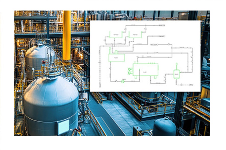
P&ID flow diagrams, also known as piping and instrumentation diagrams, play a central role in process engineering. These detailed diagrams use graphic symbols to visualise equipment, plant components, pipelines and their functions. They are a detailed description of the functions and sequences of technical processes, for example, in production areas. The clear visualisation of complex processes in a piping and instrumentation diagram enables precise design and efficient implementation of projects. Modern piping and instrumentation diagrams facilitate the creation of these flow diagrams and ensure higher design quality.
Diverse applications in the industry
Piping and instrumentation diagrams are used in numerous branches of industry. In the chemical industry, for example, they are essential for the detailed design of complex material conversion processes. They are also indispensable for precise design and documentation in the food industry and the oil and gas industry, where they are used to visualise, design, and document processes for the extraction of fuels, as well as processes for producing plastics, pharmaceuticals and similar products.
Detailed information in piping and instrumentation diagrams
A typical piping and instrumentation diagram contains a wide range of information that is required for the operation and maintenance of the system. Not all of this can be guaranteed purely via symbolic representation, which is why much information is often stored in the background. This includes information on machines and equipment, their function and labelling, details on pipelines including nominal diameter, pressure rating and material, as well as information on control and regulation functions. Operating data such as pressure, temperature and flow rate are also included in the flow diagrams. This high density of information enables precise design and efficient operation of the system.
Modern P&ID design tools have further developed the creation of flow diagrams in such an innovative way that this wealth of background information on each component and pipework is incorporated into the P&ID flow diagrams via attributes. These attributes ensure that the flow diagrams have a high level of information density and accuracy, which is essential for the design and operation of plants. In addition, all information can be analysed at any time and output as parts lists or reports.
Utilisation of innovative P&ID solutions
Many companies are turning to innovative solutions to overcome the challenges of creating piping and instrumentation diagrams. One innovative solution for the creation of intelligent piping and instrumentation diagrams is M4 P&ID. This system offers not only extensive symbol libraries and a user-friendly interface but also tools for dynamic editing and storing background information of the individual components directly in the flow diagrams. The automated creation of reports and parts lists also makes it easier to document and monitor the progress of the project.
By using modern design tools such as M4 P&ID, flow diagrams can be created and utilised even more efficiently. This further increases the quality and safety of the systems. Companies that rely on these innovative solutions benefit from optimised design and operating efficiency.
Summary: Piping and instrumentation diagrams are essential tools in process engineering; they depict the individual processes and already contain a lot of relevant information about the plant.
 Print this article
For more information, please contact:
CAD Schroer UK Ltd
39 Newnham Road
Cambridge
CB3 9EY
Tel: +44 1223 460 408
Email: info@cad-schroer.com
Web: https://www.cad-schroer.com

Process and Control Today are not responsible for the content of submitted or externally produced articles and images. Click here to email us about any errors or omissions contained within this article.