



Specifying centrifugal pumps for industrial applications
20/06/2012 Rubix
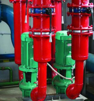
Jeremy Salisbury of Brammer, the UK's leading supplier of maintenance repair and overhaul (MRO) products and services, examines the key criteria in the selection of centrifugal pumps and the options available to specifiers and designers for creating an energy-efficient, low maintenance, pumping solution.Centrifugal (dynamic) pumps are used in a wide range of industrial applications to transfer liquids from one point to another by converting mechanical energy from a rotating impeller into pressure energy (head) that moves liquid through the pump casing and through the system pipework, valves and process equipment. The head difference between the inlet and the outlet, or total head, produced by the pump, is proportional to the impeller speed and diameter. To obtain a higher head, the rotational speed or the impeller diameter can be increased. In order to operate reliably, with optimal energy use and maximum life span, a pump's design characteristics must suit the intended service. Therefore, the correct selection of the pump is the first step in guaranteeing efficient and appropriate performance, reliable operation and maximum service life.
Understanding your centrifugal pumping system requirements
A centrifugal pump works by directing the liquid in the system into the pump's suction port and from there into the inlet of the impeller. The rotating impeller moves the liquid along the spinning vanes, which increases the velocity energy of the liquid. On leaving the impeller vanes, the liquid moves into the pump volute or diffuser casing, where the high velocity of the fluid is converted into high pressure through a diffusion process. The fluid is then guided into the discharge port of the pump and from there out into the system, or onto the next stage in the case of a multi-stage centrifugal pump. Pumping applications include constant or variable flow rate requirements, serving single or networked loads, and consisting of open loops (non-return of liquid delivery) or closed loops (return systems).
There are four general types of centrifugal pumps - rotary, overhung, submersible and horizontal self-priming. Rotary pumps function with close clearances, so that a fixed volume of liquid is displaced with each revolution of the internal element. Overhung pumps have cantilevered impellers from their bearing assemblies. Submersible pumps are designed for the pump and inside driver components to be completely surrounded by the pumped fluid. Horizontal self-priming pumps are designed to create a vacuum at the pump inlet. This enables the pump to 'suck' fluid into its casing. The suction nozzle can therefore be located above the level of liquid being pumped.
Steps to consider before selecting any pump
Of the many steps to consider before selecting a pump, the primary factors include: definition of the technological process outline and main process parameters, such as flow, pressure and temperature; determination of the required pumping services; complete description of the fluid to be handled in each pumping operation (type of fluid, temperature, density, viscosity, vapour pressure, solids in suspension, toxicity, volatility); general layout of the plant and determination of available space in three dimensions; general arrangement and dimension of the piping according to the recommended velocities for each fluid and type of pipe; determination of elevation for suction and discharge points of vessels, relative to the centre line of the pump; preliminary calculation of friction losses and plotting of system characteristic curves; definition of the working parameters of the pump, namely capacity, head, suction and discharge pressures - taking into account any possibility of variations in pressure or temperature at different pumping conditions; determination of any possible exceptional start, stop or running conditions; determination of available NPSH (Net Positive Suction Head); preliminary selection of the pump type, design, position, driver, type of sealing, and cooling of seal and bearings - if required; and establishing the type of drive unit (electric motor, steam turbine, etc) and its main operating parameters. In the case of an electric motor, special attention should be paid to its efficiency (only high-efficiency motors should be specified) and to the advisability of using a variable speed drive (VSD) to control the process.
Key selection criteria
Most pumping applications use centrifugal pumps which operate within ranges of head and velocity. For handling high-head or high-flow applications, pumps may be used in series or in parallel. When running in series, the heads are added and the total capacity is equal to the pump with the smallest capacity. In parallel, the capacities of the pumps are added and the head of all pumps will be equal at the point where the discharged liquids recombine. Parallel pumps may become an option because of specific circumstances, for example, to reduce the cost because two smaller pumps may cost less than a larger one to increase the size of an existing plant, or the process requirement might require the capacity to be varied.
The selection of pump and motor should ensure high-efficiency values, aiming for the lowest possible energy consumption per volume of pumped fluid. The best option is to specify high-efficiency motors, whose initial purchase cost may be higher, but will deliver a lower total cost of ownership through reduced energy consumption. . The decisions taken concerning efficiency and energy saving will have an influence, not only on the whole life cost of the pump-motor set but also on reducing the carbon dioxide emissions and the carbon footprint of the organisation..
In selecting a pump, engineers should first calculate the pumping conditions and then decide which type of pump to use for the application. Engineers should consider process requirements which take into account the conditions and physical properties of the liquid (flow rate, pressure, density and viscosity). The head depends on the density and viscosity of the liquid and the flow rate determines the capacity of the pump. Required flow rate is usually determined by the material and energy balances with a design margin typically up to 25 per cent. This margin is added to account for unexpected variations in properties and conditions, or to ensure the plant meets its performance criteria. Minimum flow protection is often added as continuous circulation.
Before selecting a pump, examine its performance curve, which is indicated by its head-flow rate or operating curve. The curve shows the pump's capacity, plotted against total developed head. It also shows efficiency (percentage), required power input (in brake-horsepower), and suction head requirements over a range of flow rates. Furthermore, pump curves indicate pump size and type, operating speed and impeller size, as well as showing they show the pump's BEP (Best Efficiency Point).
Pump specifiers should be aware that selecting efficient pumps and motors alone is not enough to achieve cost-effective and reliable operation. The pump characteristics must properly fit the system requirements throughout any variations occurring in the process, ensuring operation as close as possible to the BEP for the majority of operating time.
Operating a pump away from its BEP can cause adverse effects, such as cavitation. This can occur where the liquid turns into a vapour at the eye of the pump impeller, notably where pressurised liquids are being handled. Such liquids are subjected to rapid changes in pressure, causing the formation of cavities in the lower pressure regions of the fluid. When entering high-pressure areas, these bubbles collapse on a metal surface continuously, causing cyclic stressing of the metal surface which results in surface fatigue of the metal.
Guidelines for optimal selection
The following guidelines will assist in the selection of the most appropriate centrifugal pump to meet individual needs.
1. Select the pump based on rated conditions as per the data sheet.
2. Ideally the pump should have a suction specific speed of less than 11,000.
3. The BEP should be between the rated point and the normal operating point.
4. Remember that hydraulic efficiency is high at specific speed 2000 and 3000 and is low if the speed drops below 500. Higher efficiency means less vibration and noise.
5. Do not select a pump with maximum diameter impeller. The pump should be capable of a head increase at rated conditions by installing a larger impeller.
6. The head/capacity characteristic-curve should continuously rise to shut-off.
7. Minimum continuous flow should be based on hydraulic stability, not temperature rise. Furthermore, the pump should not be operated below minimum continuous flow rate.
8. Select a driver that allows operation to the end of the curve.
9. For safe operation, NPSHA (net positive suction head available) should exceed NPSHR (net positive suction head required) by more than 1m at the rated condition. As the NPSHR varies, depending on the head and flow, it is safer to select the margin at the end of the curve.
10. Consider how the pump will be driven, particularly with reference to energy efficiency. A high-efficiency motor should always be specified, while fitting a VSD may also be advisable.
Summary
Centrifugal pumps are used in more industrial applications than any other kind of pump. Primarily, this is because they offer low initial and upkeep costs. Traditionally, these pumps have been limited to low-pressure-head applications but modern pump designs have overcome this problem unless very high pressures are required.
In order for a centrifugal pump to run correctly, without wasting energy or sustaining internal damage, its design characteristics must be suitable for the intended service. Therefore, the correct selection of the pump is integral to optimising performance, operation and product life.
For further information, please visit: www.brammer.co.uk.
 Print this article
Share article:

Process and Control Today are not responsible for the content of submitted or externally produced articles and images. Click here to email us about any errors or omissions contained within this article.